

Ensuring a robot frame is strong and safe is critical, especially in Mechatronics and Biomedical device design. I used SOLIDWORKS Simulation to run a structural analysis on my humanoid robot frame before fabrication, confirming it could handle all loads while staying lightweight.
Click here to read about the design of the robot.
Obviously, the entire robot was already designed in SOLIDWORKS before performing this study.
Step 1: Prepare the Model
- Open the assembly in SOLIDWORKS
- Assign materials to each part: right-click → Material → Edit Material → Apply
- Make sure all parts are properly constrained
Correct materials and assembly setup are essential for accurate results. In this case, the material used was Aluminum, since the frame was to be built with 20x20mm aluminum tubes.
Step 2: Enable Simulation
- Go to Tools → Add-Ins
- Check SOLIDWORKS Simulation → OK
The Simulation tab will now appear.
Step 3: Create a Static Study
- Simulation tab → New Study → Static → OK
This allows testing the frame under expected static and operational loads.
Step 4: Apply Fixtures
- Right-click Fixtures → Fixed Geometry
- Select the faces where the frame will be mounted → OK
Fixtures simulate real-world support points. In this case, we considered the base as the fixed geometry as it was least affected by loads during motion.
Step 5: Apply Loads
- Right-click External Loads → Gravity → set direction → OK
- Right-click External Loads → Force / Torque → apply at motor mounts or joints → OK
Loads represent the robot’s weight and forces during movement.
The study was repeated to test multiple sets of loads:
- A horizontal force that is generated when the robot moved forward/back.
- A vertical force that is exerted on the base of the robot (wheel area) when it is fully loaded.
- Lateral forces when the robot would rotate.
Step 6: Mesh the Model
- Right-click Mesh → Create Mesh → OK
- Optionally refine the mesh in high-stress areas like joints
Finer meshes give more accurate stress results, but are more taxing on computer resources and may take more time to complete.
Step 7: Run the Simulation
- Click the Run button in the Simulation toolbar.
- Wait for the simulation to complete – get a coffee in the meantime.
Step 8: Review Results
- Right-click Results → Stress → Von Mises → Show
- Right-click Results → Displacement → Show
- Right-click Results → Factor of Safety → Show
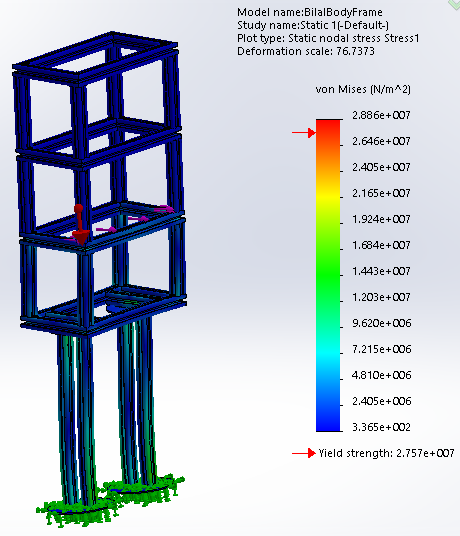
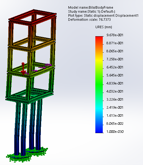
Check that stresses are below material limits and deformations are acceptable.
Step 9: Iterate Design
If stress is too high:
- Add fillets to corners
- Reinforce joints
- Adjust wall thickness
Re-run the simulation until the frame meets safety and performance targets.
Conclusion
Using SOLIDWORKS Simulation, I validated that the robot frame was structurally sound, lightweight, and safe for operation.
This workflow is essential for engineers in Mechatronics, Biomedical engineering, and Medical Device development to reduce risk and ensure reliable designs before manufacturing.